Schematic Design Part 2
Now I’ve finalized the latest modifications to the schematic. The Modbus circuit was challenging to design in the most cost-effective way, but I believe I’ve found a good combo that still maintains the capabilities of an isolated RS485 interface IC.
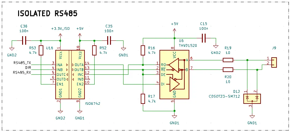
Modbus RTU
I’m using a robust IC, the THVD1520, with additional protection, and the ISO6742 as a digital isolator. This setup is cheaper than using an isolated RS485 IC directly since the ISO6742 becomes more affordable when purchased in quantities of 10 or more.
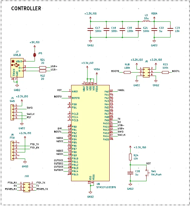
Microcontroller
The microcontroller circuit follows the standard specified in the datasheet and the BluePill board diagram. I included an SWD programming connector in case it’s needed, as well as a connector to select whether the RX and TX pins will be used for Modbus or the FTDI board. I also added a USB Type-B connector for programming via the Arduino IDE.
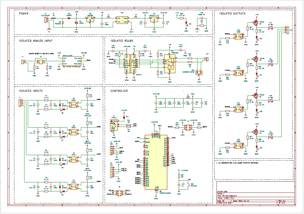
Conclusion
The final circuit looks like this:
So far, I’m satisfied with the schematic. During my research for an isolated RS485, I found an isolation IC designed specifically for PLCs, the ISO1211 from Texas Instruments. It seems to be a good option. But I will not change my circuit now in order to keep focus and meet deadlines fast. In a version 2 I will give it a try.
The next step is to start defining the components and footprints. The goal is to have everything ready to estimate the size of the PCB I’ll need. This is crucial for defining the enclosure.
I won’t document the footprint definition stage here since it is well-covered in the KiCad documentation and involves repetitive work. All this work will be made available in the project’s Repository.
I’ll also identify each component with an internal code to import into an ERP system later in case you see some strange identifiers there.
If you have any questions or recommendations, feel free to contact me via email.